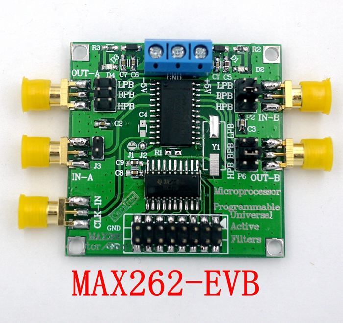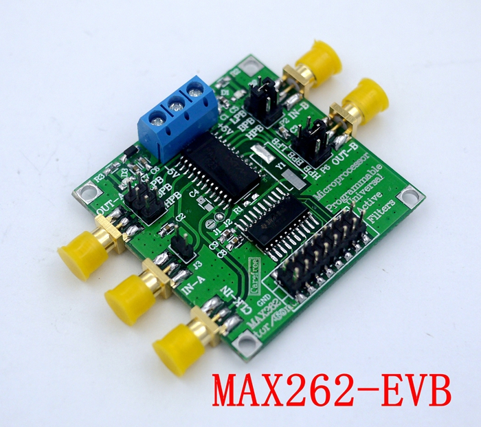

Product Details
Features:
1. with a filter design software, with a microprocessor interface;
2. can control 64 different center frequency f0, 128 different quality factor Q and 4 kinds of work patterns;
3. the center frequency f0 and quality factor Q can be independently programmed;
4. can provide three clock input (external clock input, RC oscillator and crystal devices);
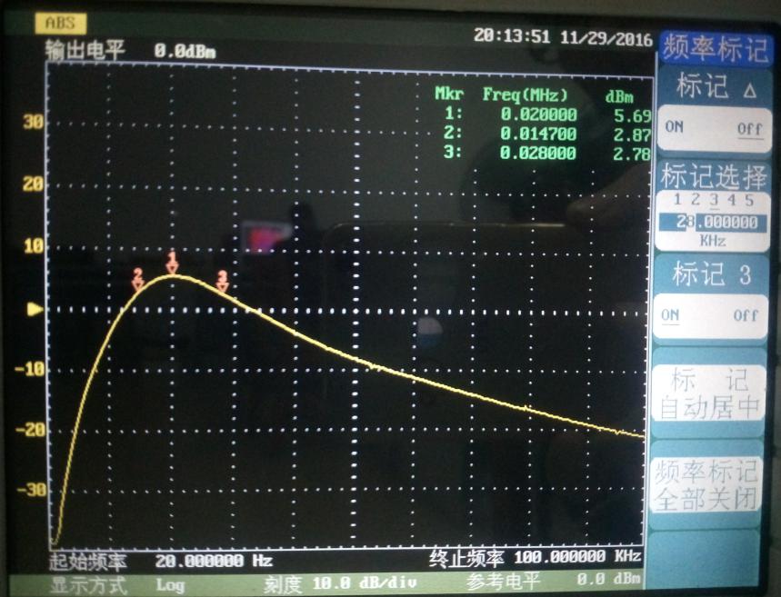
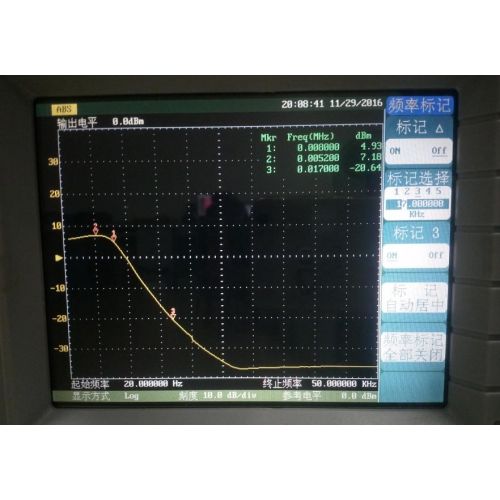
5. the central frequency f0 range of 1Hz ~ 140kHz, the maximum input clock 4MHz;
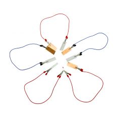
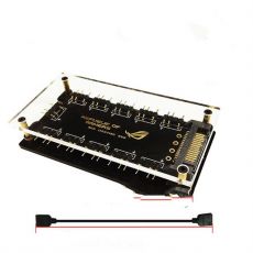
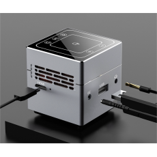
6. the filter circuit structure is simple, less external components, small size;
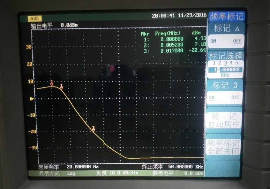
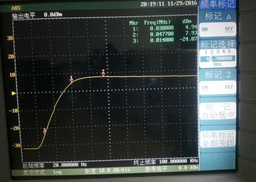
7. can achieve low-pass, high-pass, band-pass, band-stop and all-pass filter;
8. can be A, B single-stage input and output, but also AB cascade of two levels of input and output;
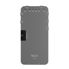
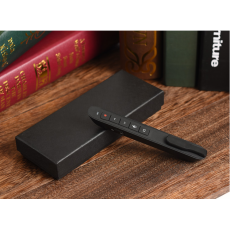
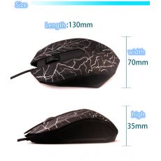
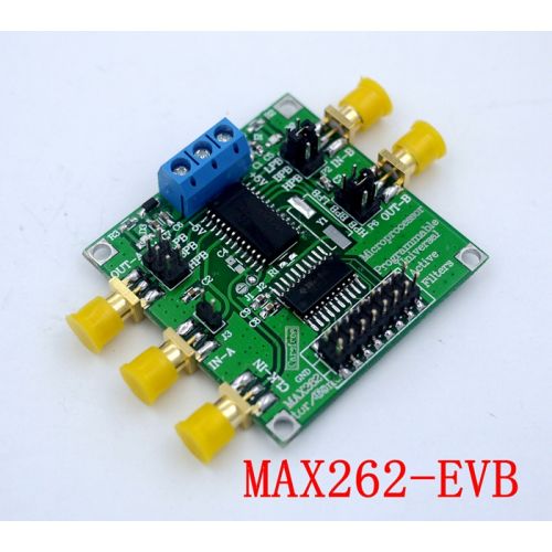
9. Product size: 50*50MM
10. Product weight: 22 grams
The main chip pin description:
V + - positive power input.
V- -Negative power input.
GND - Analog ground.
CLKA - external crystal oscillator and filter A part of the clock input, within the filter, the clock frequency is divided by 2.
CLKB - the clock input to filter B, also within the filter, the clock frequency is divided by 2.
CLKOUT - Clock output for crystal oscillator and R-C oscillation.
OSCOUT - Connects to a crystal or R-C oscillator for self-synchronization.
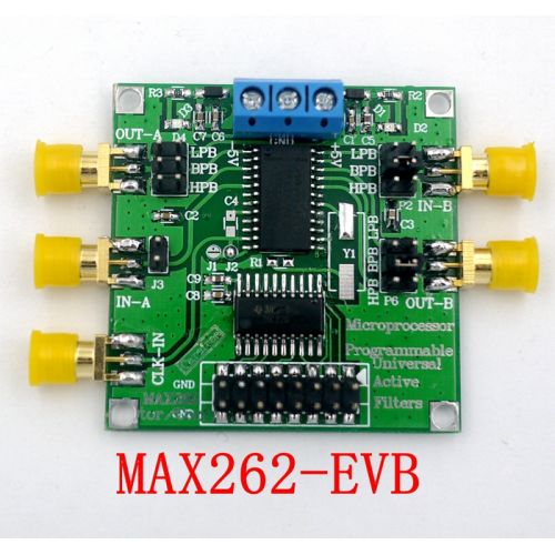
INA, INB - The signal input of the filter.
BPA, BPB - band-pass filter output.
LPA, LPB - low-pass filter output.
HPA, HPB - high-pass, with resistance, all-pass filter output.
WR - Writing to the active input. When connected to V +, the data can be entered into a programmable memory through the logical interface to complete the filter mode, f0 and Q settings. In addition, it can receive TTL level signals, and the rising edge latch input data.
A0, A1, A2, A3 - address input, can be used to complete the filter mode, f0 and Q of the corresponding settings.
D0, D1 - Data input, can be used to set the corresponding bits f0 and Q.
OP OUT - The amplifier output of the MAX262.
OP IN - The inverting input of the MAX262 amplifier.
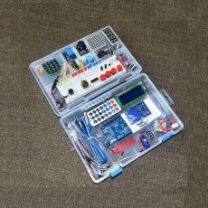
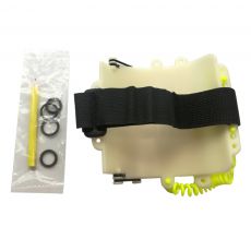
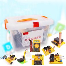
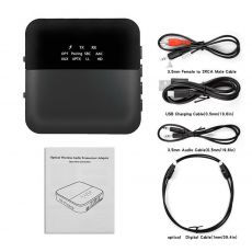
Packing list:
Program-controlled filter * 1